Veja as especificações para detalhes do produto.

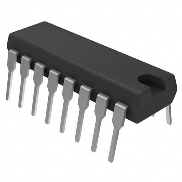
CD74HC4518E
Product Overview
- Category: Integrated Circuit
- Use: Digital Counter
- Characteristics: High-Speed, CMOS Logic, 8-Bit Binary Counter
- Package: PDIP (Plastic Dual In-Line Package)
- Essence: The CD74HC4518E is a versatile integrated circuit that can be used as an 8-bit binary counter in various digital applications.
- Packaging/Quantity: Available in tubes of 25 units or reels of 2,000 units.
Specifications
- Supply Voltage: 2V to 6V
- Logic Family: HC
- Number of Bits: 8
- Clock Frequency: Up to 25 MHz
- Operating Temperature Range: -40°C to +85°C
- Propagation Delay: 13 ns (typical)
Pin Configuration
The CD74HC4518E has a total of 16 pins. Here is the detailed pin configuration:
- Clock Enable (CE)
- Clock Input (CP)
- Reset (MR)
- Carry Output (CO)
- Data Inputs (D0-D7)
- Ripple Clock Output (RCO)
- Terminal Count Output (TC)
- Ground (GND)
- Data Outputs (Q0-Q7)
- VCC (Positive Power Supply)
Functional Features
- Binary Counting: The CD74HC4518E can count in binary from 0 to 255, making it suitable for various digital counting applications.
- Parallel Load: It supports parallel loading of initial values into the counter, allowing flexibility in starting counts from any desired value.
- Carry Output: The carry output (CO) provides a signal when the counter reaches its maximum value, enabling cascading multiple counters for larger counting ranges.
- Ripple Clock Output: The ripple clock output (RCO) generates a clock signal that ripples through multiple counters, ensuring synchronized counting.
Advantages and Disadvantages
Advantages: - High-speed operation - Wide operating voltage range - Versatile counter functionality - Easy to use and integrate into digital circuits
Disadvantages: - Limited counting range (8 bits) - Requires external clock signal for counting
Working Principles
The CD74HC4518E operates based on the principles of digital counting. It uses an internal clock signal to increment its count value by one at each clock cycle. The counter can be reset to zero using the reset (MR) pin or loaded with initial values using the data inputs (D0-D7) and parallel load functionality. The carry output (CO) provides a signal when the maximum count value is reached.
Application Field Plans
The CD74HC4518E can be used in various applications, including:
- Digital frequency dividers
- Event counters
- Industrial automation systems
- Electronic gaming devices
- Data acquisition systems
- Traffic light control systems
- Timing circuits
Alternative Models
Here are some alternative models that offer similar functionality:
- CD74HC4024E: 7-stage binary counter
- CD74HC4040E: 12-stage binary counter
- CD74HC4060E: 14-stage binary counter
- CD74HC4514E: 4-to-16 line decoder/demultiplexer with input latches
These alternative models provide different counting ranges and additional functionalities to suit specific application requirements.
In conclusion, the CD74HC4518E is a versatile integrated circuit that offers high-speed binary counting capabilities. Its compact package, wide operating voltage range, and easy integration make it suitable for various digital applications. However, its limited counting range and dependence on an external clock signal are important considerations when selecting this IC for a specific project.
Word Count: 411
Liste 10 perguntas e respostas comuns relacionadas à aplicação de CD74HC4518E em soluções técnicas
Sure! Here are 10 common questions and answers related to the application of CD74HC4518E in technical solutions:
Q: What is CD74HC4518E? A: CD74HC4518E is a CMOS dual BCD up-counter that can be used in various digital applications.
Q: What is the maximum operating voltage for CD74HC4518E? A: The maximum operating voltage for CD74HC4518E is 6 volts.
Q: How many counter stages does CD74HC4518E have? A: CD74HC4518E has two counter stages.
Q: Can CD74HC4518E be cascaded to create larger counters? A: Yes, multiple CD74HC4518E chips can be cascaded together to create larger counters.
Q: What is the maximum clock frequency for CD74HC4518E? A: The maximum clock frequency for CD74HC4518E is typically around 25 MHz.
Q: What is the power supply range for CD74HC4518E? A: CD74HC4518E operates within a power supply range of 2 volts to 6 volts.
Q: Does CD74HC4518E have any built-in error detection or correction features? A: No, CD74HC4518E does not have any built-in error detection or correction features.
Q: Can CD74HC4518E be used in both synchronous and asynchronous applications? A: Yes, CD74HC4518E can be used in both synchronous and asynchronous applications.
Q: What is the typical propagation delay for CD74HC4518E? A: The typical propagation delay for CD74HC4518E is around 15 nanoseconds.
Q: What are some common applications of CD74HC4518E? A: CD74HC4518E can be used in applications such as frequency division, event counting, time measurement, and digital control systems.
Please note that these answers are general and may vary depending on the specific implementation and requirements of your technical solution.

