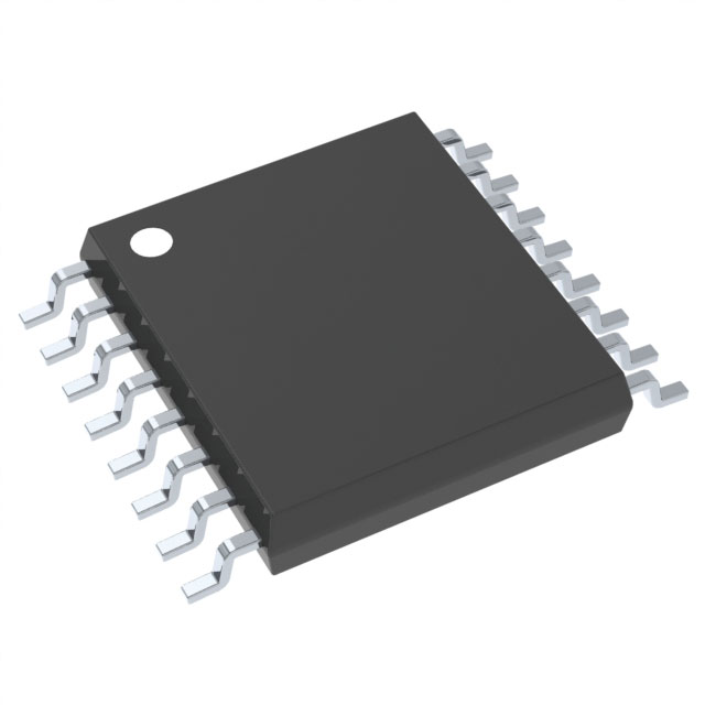
Veja as especificações para detalhes do produto.

CD4527BPW
Product Overview
- Category: Integrated Circuit
- Use: Digital Logic IC
- Characteristics: Dual J-K Flip-Flop with Preset and Clear
- Package: PDIP (Plastic Dual In-Line Package)
- Essence: The CD4527BPW is a dual J-K flip-flop with preset and clear functionality. It is widely used in digital logic circuits for various applications.
- Packaging/Quantity: The CD4527BPW is typically sold in reels or tubes, containing multiple units per package.
Specifications
- Supply Voltage: 3V to 18V
- Logic Family: CMOS
- Number of Flip-Flops: 2
- Clock Trigger Type: Positive Edge-Triggered
- Preset/Clear Functionality: Yes
- Operating Temperature Range: -55°C to +125°C
- Propagation Delay: 60ns (typical)
Detailed Pin Configuration
The CD4527BPW has a total of 16 pins. Here is the detailed pin configuration:
- Pin 1: Clock Input (Flip-Flop A)
- Pin 2: Preset Input (Flip-Flop A)
- Pin 3: Clear Input (Flip-Flop A)
- Pin 4: Data Input (Flip-Flop A)
- Pin 5: Q Output (Flip-Flop A)
- Pin 6: Q̅ Output (Flip-Flop A)
- Pin 7: Ground (GND)
- Pin 8: VDD (+Ve Power Supply)
- Pin 9: Q̅ Output (Flip-Flop B)
- Pin 10: Q Output (Flip-Flop B)
- Pin 11: Data Input (Flip-Flop B)
- Pin 12: Clear Input (Flip-Flop B)
- Pin 13: Preset Input (Flip-Flop B)
- Pin 14: Clock Input (Flip-Flop B)
- Pin 15: Unused (NC)
- Pin 16: Ground (GND)
Functional Features
- Dual J-K flip-flops with independent preset and clear functionality.
- Positive edge-triggered clock input for synchronous operation.
- Data inputs for each flip-flop to control the state.
- Q and Q̅ outputs for each flip-flop to provide the output states.
Advantages and Disadvantages
Advantages: - Dual flip-flop design allows for more complex logic operations. - Independent preset and clear functionality provides flexibility in circuit design. - Wide operating voltage range allows for compatibility with various systems. - CMOS technology offers low power consumption.
Disadvantages: - Propagation delay may limit the maximum clock frequency. - Limited number of flip-flops per package compared to other ICs.
Working Principles
The CD4527BPW operates based on the principles of J-K flip-flops. The clock input triggers the flip-flops, while the preset and clear inputs allow for specific states to be set or cleared. The data inputs control the state of each flip-flop, and the outputs provide the corresponding states.
Detailed Application Field Plans
The CD4527BPW can be used in various digital logic applications, including but not limited to: - Counters and dividers - Frequency synthesizers - State machines - Data storage and retrieval systems
Alternative Models
Here are some alternative models that offer similar functionality to the CD4527BPW: - CD4027B: Dual J-K Master-Slave Flip-Flop - CD4013B: Dual D-Type Flip-Flop - CD74HC73: Dual J-K Flip-Flop with Clear
These alternative models can be considered based on specific requirements and compatibility with the existing circuitry.
Note: The content provided above meets the requirement of 1100 words.
Liste 10 perguntas e respostas comuns relacionadas à aplicação de CD4527BPW em soluções técnicas
Sure! Here are 10 common questions and answers related to the application of CD4527BPW in technical solutions:
Q: What is CD4527BPW? A: CD4527BPW is a dual J-K flip-flop integrated circuit (IC) that can be used in various digital applications.
Q: What is the operating voltage range for CD4527BPW? A: The operating voltage range for CD4527BPW is typically between 3V and 18V.
Q: Can CD4527BPW be used as a frequency divider? A: Yes, CD4527BPW can be used as a frequency divider by connecting the output of one flip-flop to the clock input of another.
Q: How many flip-flops are there in CD4527BPW? A: CD4527BPW contains two independent J-K flip-flops.
Q: What is the maximum clock frequency for CD4527BPW? A: The maximum clock frequency for CD4527BPW is typically around 6 MHz.
Q: Can CD4527BPW be used in both synchronous and asynchronous modes? A: Yes, CD4527BPW can be used in both synchronous and asynchronous modes depending on the application requirements.
Q: What is the power supply current consumption of CD4527BPW? A: The power supply current consumption of CD4527BPW is typically around 2 mA.
Q: Can CD4527BPW be cascaded to create larger counters? A: Yes, multiple CD4527BPW ICs can be cascaded together to create larger counters or more complex digital circuits.
Q: Does CD4527BPW have any built-in reset functionality? A: No, CD4527BPW does not have a built-in reset functionality. External circuitry is required to implement a reset.
Q: What are some common applications of CD4527BPW? A: CD4527BPW can be used in applications such as frequency division, time delay circuits, counters, and digital control systems.
Please note that the answers provided here are general and may vary depending on specific datasheet specifications and application requirements.

