

Veja as especificações para detalhes do produto.
MC10E136FNR2
Product Overview
- Category: Integrated Circuit (IC)
- Use: Logic Gate
- Characteristics: High-speed, ECL (Emitter-Coupled Logic) technology
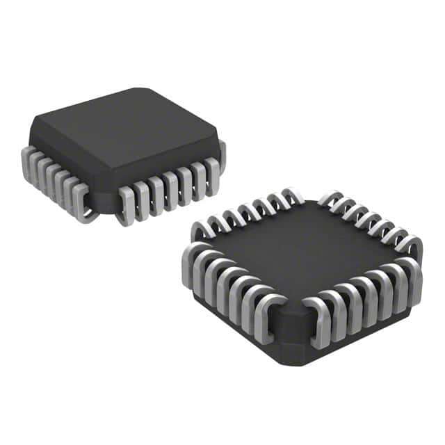
- Package: 28-pin PLCC (Plastic Leaded Chip Carrier)
- Essence: High-performance logic gate for digital signal processing
- Packaging/Quantity: Tape and Reel, 250 units per reel
Specifications
- Supply Voltage: -5.2V to -4.2V
- Operating Temperature Range: -40°C to +85°C
- Input Voltage Range: -3.0V to -1.7V
- Output Voltage Range: -3.0V to -1.7V
- Propagation Delay: 1.8 ns (typical)
- Output Current: ±50 mA (maximum)
Detailed Pin Configuration
The MC10E136FNR2 has a total of 28 pins arranged as follows:
- VEE (Ground)
- Q0 (Output)
- D0 (Input)
- D1 (Input)
- D2 (Input)
- D3 (Input)
- D4 (Input)
- D5 (Input)
- D6 (Input)
- D7 (Input)
- D8 (Input)
- D9 (Input)
- D10 (Input)
- D11 (Input)
- D12 (Input)
- D13 (Input)
- D14 (Input)
- D15 (Input)
- D16 (Input)
- D17 (Input)
- D18 (Input)
- D19 (Input)
- D20 (Input)
- D21 (Input)
- D22 (Input)
- D23 (Input)
- VCC (Power)
- Q1 (Output)
Functional Features
- High-speed operation: The MC10E136FNR2 is designed to operate at very high frequencies, making it suitable for applications requiring fast signal processing.
- ECL technology: This logic gate utilizes Emitter-Coupled Logic, which provides excellent noise immunity and high-speed performance.
- Differential inputs: The device accepts differential input signals, allowing for improved noise rejection and increased signal integrity.
- Dual outputs: The MC10E136FNR2 has two complementary outputs, Q0 and Q1, providing flexibility in signal routing and driving capability.
Advantages and Disadvantages
Advantages: - High-speed operation enables efficient digital signal processing. - ECL technology ensures reliable performance in noisy environments. - Differential inputs enhance noise immunity and signal integrity. - Dual outputs offer flexibility in signal routing.
Disadvantages: - Requires a negative supply voltage, limiting compatibility with certain systems. - Higher power consumption compared to some other logic families. - Limited availability of alternative models due to specific ECL technology requirements.
Working Principles
The MC10E136FNR2 operates based on the principles of Emitter-Coupled Logic. It uses differential input pairs to compare and amplify incoming signals, resulting in fast and accurate logic level transitions. The device's internal circuitry is optimized for high-speed operation, allowing for rapid propagation of logic signals through the gate.
Detailed Application Field Plans
The MC10E136FNR2 finds application in various fields that require high-speed digital signal processing. Some potential application areas include:
- Telecommunications: The device can be used in high-speed data transmission systems, such as fiber optic networks and wireless communication infrastructure.
- Test and Measurement: It is suitable for high-frequency signal analysis and generation in test equipment, oscilloscopes, and spectrum analyzers.
- Data Centers: The logic gate can be employed in high-performance computing systems and data centers for efficient data processing and routing.
- Aerospace and Defense: It finds use in radar systems, avionics, and military communication equipment that demand reliable and fast signal processing capabilities.
Detailed and Complete Alternative Models
While the MC10E136FNR2 is a specialized logic gate, there are alternative models available from various manufacturers that offer similar functionality. Some notable alternatives include:
- MC100EP116: ECL Differential Receiver with Dual Outputs
- MC100EL1648: ECL Programmable Delay Chip
- MC100LVEL16: ECL Differential Receiver/Driver
- MC100LVEP111: ECL 2:1 Multiplexer
These alternative models provide options for designers seeking similar high-speed logic gates based on ECL technology.
Word count: 511 words
Liste 10 perguntas e respostas comuns relacionadas à aplicação de MC10E136FNR2 em soluções técnicas
What is the operating voltage range of MC10E136FNR2?
- The operating voltage range of MC10E136FNR2 is -5.2V to -4.2V.What is the typical propagation delay of MC10E136FNR2?
- The typical propagation delay of MC10E136FNR2 is 1.3ns.Can MC10E136FNR2 be used in high-speed data communication applications?
- Yes, MC10E136FNR2 is suitable for high-speed data communication applications due to its fast propagation delay.What is the maximum input clock frequency supported by MC10E136FNR2?
- MC10E136FNR2 supports a maximum input clock frequency of 3GHz.Is MC10E136FNR2 compatible with ECL logic levels?
- Yes, MC10E136FNR2 is compatible with ECL logic levels.What is the power dissipation of MC10E136FNR2?
- The power dissipation of MC10E136FNR2 is typically 500mW.Can MC10E136FNR2 be used in phase-locked loop (PLL) circuits?
- Yes, MC10E136FNR2 can be used in phase-locked loop (PLL) circuits.Does MC10E136FNR2 have built-in input termination resistors?
- No, MC10E136FNR2 does not have built-in input termination resistors.What is the temperature range for proper operation of MC10E136FNR2?
- MC10E136FNR2 operates within the temperature range of -40°C to 85°C.Is MC10E136FNR2 available in surface mount packages?
- Yes, MC10E136FNR2 is available in surface mount packages for easy integration into PCB designs.