

Veja as especificações para detalhes do produto.
DS87C520-QCL+T&R
Product Overview
Category: Microcontroller
Use: Embedded systems, industrial automation, consumer electronics
Characteristics: High-performance, low-power consumption, versatile
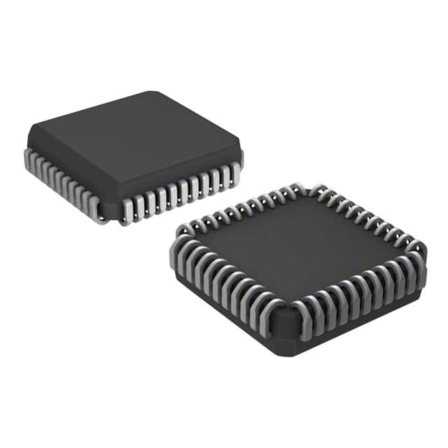
Package: QFP (Quad Flat Package)
Essence: Advanced microcontroller with integrated peripherals
Packaging/Quantity: Tape and reel, 250 units per reel
Specifications
- Architecture: 8-bit
- CPU Speed: Up to 33 MHz
- Program Memory: 8 KB Flash
- Data Memory: 256 bytes RAM
- I/O Pins: 32
- Timers/Counters: 3
- Serial Communication: UART, SPI, I2C
- Analog-to-Digital Converter: 8 channels, 10-bit resolution
- Operating Voltage: 2.7V to 5.5V
- Operating Temperature: -40°C to +85°C
Detailed Pin Configuration
The DS87C520-QCL+T&R microcontroller has a total of 44 pins. The pin configuration is as follows:
- VDD - Power supply voltage
- P0.0 - General-purpose I/O pin
- P0.1 - General-purpose I/O pin
- P0.2 - General-purpose I/O pin
- P0.3 - General-purpose I/O pin
- P0.4 - General-purpose I/O pin
- P0.5 - General-purpose I/O pin
- P0.6 - General-purpose I/O pin
- P0.7 - General-purpose I/O pin
- RST - Reset pin
- XTAL1 - Crystal oscillator input
- XTAL2 - Crystal oscillator output
- PSEN - Program store enable
- ALE/PROG - Address latch enable/Program pulse input
- EA/VPP - External access enable/Programming voltage input
- P2.0 - General-purpose I/O pin
- P2.1 - General-purpose I/O pin
- P2.2 - General-purpose I/O pin
- P2.3 - General-purpose I/O pin
- P2.4 - General-purpose I/O pin
- P2.5 - General-purpose I/O pin
- P2.6 - General-purpose I/O pin
- P2.7 - General-purpose I/O pin
- P3.0 - General-purpose I/O pin
- P3.1 - General-purpose I/O pin
- P3.2 - General-purpose I/O pin
- P3.3 - General-purpose I/O pin
- P3.4 - General-purpose I/O pin
- P3.5 - General-purpose I/O pin
- P3.6 - General-purpose I/O pin
- P3.7 - General-purpose I/O pin
- VSS - Ground
Functional Features
- High-performance 8-bit microcontroller with integrated peripherals
- Versatile I/O capabilities for interfacing with external devices
- Low-power consumption for energy-efficient applications
- Built-in timers/counters for precise timing operations
- Serial communication interfaces (UART, SPI, I2C) for data exchange
- Analog-to-Digital Converter for analog signal processing
- Robust operating voltage and temperature range for various environments
Advantages and Disadvantages
Advantages: - High-performance and versatile microcontroller - Integrated peripherals reduce external component count - Low-power consumption extends battery life - Wide operating voltage and temperature range - Ample program and data memory for most applications
Disadvantages: - Limited program memory compared to some other microcontrollers - 8-bit architecture may not be suitable for certain complex applications
Working Principles
The DS87C520-QCL+T&R microcontroller operates based on an 8-bit architecture. It executes instructions stored in its program memory and interacts with external devices through its I/O pins. The integrated peripherals, such as timers/counters, serial communication interfaces, and analog-to-digital converter, enhance its functionality and enable it to perform a wide range of tasks. The microcontroller's low-power consumption and robust operating characteristics make it suitable for various applications.
Detailed Application Field Plans
The DS87C520-QCL+T&R microcontroller finds applications in several fields, including:
- Embedded Systems: Used in various embedded systems like home automation, industrial control, and automotive electronics.
- Industrial Automation: Enables control and monitoring of machinery, process automation, and data acquisition in industrial settings.
- Consumer Electronics: Powers consumer electronic devices such as smart appliances, remote controls, and gaming consoles.
- Internet
Liste 10 perguntas e respostas comuns relacionadas à aplicação de DS87C520-QCL+T&R em soluções técnicas
What is the operating voltage range of DS87C520-QCL+T&R?
- The operating voltage range of DS87C520-QCL+T&R is 4.5V to 5.5V.What is the maximum clock frequency supported by DS87C520-QCL+T&R?
- DS87C520-QCL+T&R supports a maximum clock frequency of 33MHz.Can DS87C520-QCL+T&R be used in automotive applications?
- Yes, DS87C520-QCL+T&R is suitable for automotive applications.What are the available package options for DS87C520-QCL+T&R?
- DS87C520-QCL+T&R is available in a 44-pin PLCC package.Does DS87C520-QCL+T&R have built-in EEPROM memory?
- No, DS87C520-QCL+T&R does not have built-in EEPROM memory.What is the temperature range for operation of DS87C520-QCL+T&R?
- DS87C520-QCL+T&R has an extended temperature range of -40°C to 85°C.Is DS87C520-QCL+T&R RoHS compliant?
- Yes, DS87C520-QCL+T&R is RoHS compliant.Can DS87C520-QCL+T&R be used in industrial control systems?
- Yes, DS87C520-QCL+T&R is suitable for use in industrial control systems.What programming language is commonly used for DS87C520-QCL+T&R?
- Assembly language is commonly used for programming DS87C520-QCL+T&R.Does DS87C520-QCL+T&R have on-chip analog-to-digital converters (ADC)?
- No, DS87C520-QCL+T&R does not have on-chip ADCs.