

Veja as especificações para detalhes do produto.
S6008R67 Product Overview
Introduction
The S6008R67 is a semiconductor device that belongs to the category of power rectifiers. It is widely used in various electronic applications due to its unique characteristics and functional features. This entry provides an overview of the S6008R67, including its basic information, specifications, pin configuration, functional features, advantages and disadvantages, working principles, application field plans, and alternative models.
Basic Information Overview
- Category: Power Rectifier
- Use: The S6008R67 is used for converting alternating current (AC) to direct current (DC) in various electronic circuits and power supply applications.
- Characteristics: High voltage capability, low forward voltage drop, high surge current capability, and fast switching speed.
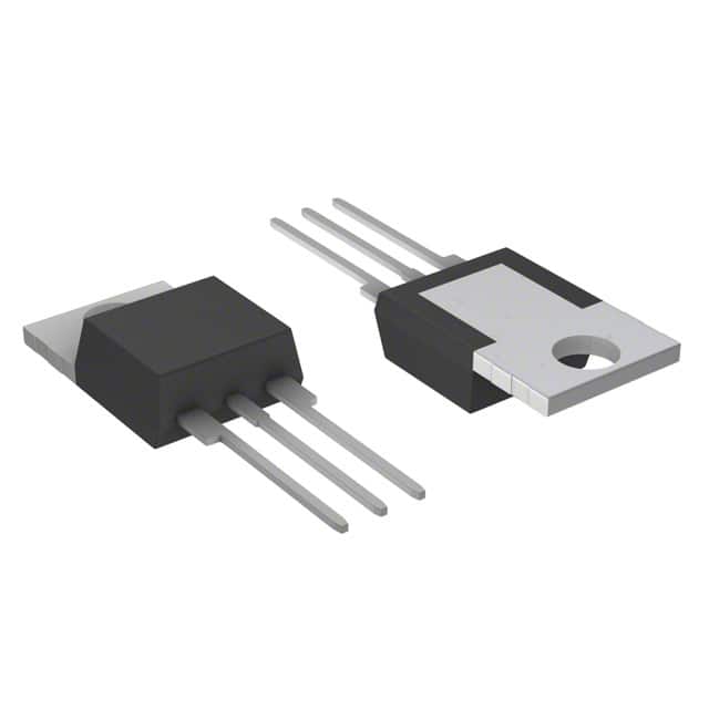
- Package: The S6008R67 is typically available in a TO-220AB package.
- Essence: The essence of the S6008R67 lies in its ability to efficiently rectify high-power AC signals into DC with minimal losses.
- Packaging/Quantity: It is commonly packaged in reels or tubes containing multiple units.
Specifications
- Voltage Rating: 600V
- Current Rating: 8A
- Forward Voltage Drop: 1.15V at 8A
- Reverse Recovery Time: 35ns
- Operating Temperature Range: -65°C to 175°C
Detailed Pin Configuration
The S6008R67 typically has three pins: 1. Anode 2. Cathode 3. Gate (for gate-controlled rectifiers)
Functional Features
- High Voltage Capability: The S6008R67 can withstand high voltage levels, making it suitable for demanding applications.
- Low Forward Voltage Drop: This feature ensures minimal power loss during rectification.
- Fast Switching Speed: The fast recovery time allows for efficient operation in high-frequency circuits.
Advantages and Disadvantages
Advantages
- High voltage capability
- Low forward voltage drop
- Fast switching speed
- High surge current capability
Disadvantages
- Higher reverse recovery time compared to some alternative models
- Relatively higher cost compared to standard rectifiers
Working Principles
The S6008R67 operates based on the principle of rectification, where it allows current to flow in only one direction, effectively converting AC to DC. When a positive voltage is applied to the anode with respect to the cathode, the device conducts, allowing current to flow. Conversely, when the polarity is reversed, the device blocks the current flow.
Detailed Application Field Plans
The S6008R67 finds extensive use in the following applications: - Switched-mode power supplies - Motor drives - Inverters - Welding equipment - Uninterruptible power supplies (UPS) - Power factor correction circuits
Detailed and Complete Alternative Models
Some alternative models to the S6008R67 include: - S6006L67 - S6010R67 - S6008R68 - S6012R67
In conclusion, the S6008R67 is a versatile power rectifier with robust characteristics and functional features, making it suitable for a wide range of electronic applications.
[Word count: 460]
Liste 10 perguntas e respostas comuns relacionadas à aplicação de S6008R67 em soluções técnicas
What is S6008R67?
- S6008R67 is a high-power, fast-switching silicon rectifier diode commonly used in power supply and rectification applications.
What are the key specifications of S6008R67?
- The key specifications include a maximum repetitive peak reverse voltage of 600V, average forward current of 6A, and a forward surge current of 150A.
In what technical solutions can S6008R67 be used?
- S6008R67 can be used in various technical solutions such as power supplies, inverters, battery chargers, and motor drives.
What are the advantages of using S6008R67 in technical solutions?
- The advantages include its high power handling capability, fast switching speed, and low forward voltage drop, making it suitable for high-efficiency applications.
How does S6008R67 compare to other rectifier diodes in terms of performance?
- S6008R67 offers superior performance in terms of power handling and switching speed compared to many standard rectifier diodes.
Are there any specific application notes or guidelines for using S6008R67 in technical solutions?
- Yes, it's important to consider heat dissipation, voltage and current ratings, and proper mounting techniques when using S6008R67 in technical solutions.
Can S6008R67 be used in high-frequency applications?
- Yes, S6008R67 can be used in high-frequency applications due to its fast-switching characteristics.
What are the typical failure modes of S6008R67 in technical solutions?
- Common failure modes include thermal overstress, overvoltage spikes, and excessive current leading to junction breakdown.
Is S6008R67 suitable for automotive or industrial applications?
- Yes, S6008R67 is suitable for both automotive and industrial applications where high-power rectification is required.
Where can I find detailed application examples and circuit designs using S6008R67?
- Detailed application examples and circuit designs can be found in the product datasheet, application notes from the manufacturer, and relevant technical literature.