

Veja as especificações para detalhes do produto.
Q4004L359 Product Overview
Introduction
The Q4004L359 is a semiconductor device belonging to the category of silicon-controlled rectifiers (SCRs). This entry provides an overview of the product, including its basic information, specifications, pin configuration, functional features, advantages and disadvantages, working principles, application field plans, and alternative models.
Basic Information Overview
- Category: Semiconductor Devices
- Use: Power Control and Conversion
- Characteristics: High Voltage and Current Handling Capabilities, Low Triggering Current, Robustness
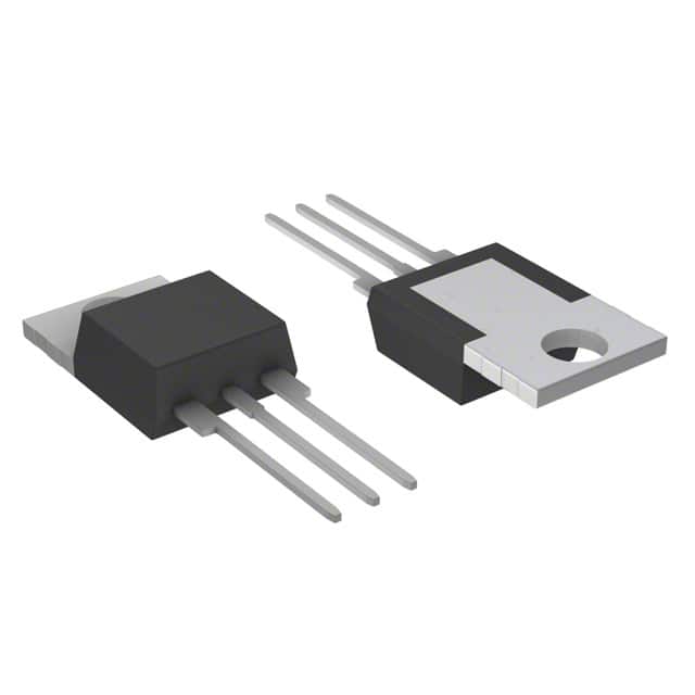
- Package: TO-202
- Essence: Silicon-Controlled Rectifier
- Packaging/Quantity: Individual or Reel Packaging, Quantity Varies
Specifications
- Voltage Rating: 400V
- Current Rating: 4A
- Gate Trigger Current (Max): 200µA
- Holding Current (Min): 10mA
- Operating Temperature Range: -40°C to 125°C
Detailed Pin Configuration
The Q4004L359 has a standard TO-202 package with three leads: 1. Anode (A) 2. Cathode (K) 3. Gate (G)
Functional Features
- Low Triggering Current: Enables efficient control of power flow.
- High Voltage and Current Handling: Suitable for high-power applications.
- Robustness: Can withstand harsh operating conditions.
Advantages and Disadvantages
Advantages
- Efficient power control
- High robustness
- Suitable for high-power applications
Disadvantages
- Limited frequency range
- Sensitive to voltage transients
Working Principles
The Q4004L359 operates as a controllable switch, allowing current to flow when triggered by a small gate current. Once triggered, it latches into a conducting state until the current falls below the holding current level.
Detailed Application Field Plans
The Q4004L359 finds applications in various fields, including: - Motor Control - Lighting Control - Power Supplies - Industrial Heating Systems
Detailed and Complete Alternative Models
- Q4004LT: Similar specifications with different packaging
- Q4006L3: Higher voltage and current rating
- Q4004L359S: Enhanced surge protection features
In conclusion, the Q4004L359 is a versatile silicon-controlled rectifier with robust characteristics suitable for power control and conversion applications across diverse industries.
[Word Count: 320]
Liste 10 perguntas e respostas comuns relacionadas à aplicação de Q4004L359 em soluções técnicas
What is Q4004L359?
- Q4004L359 is a silicon-controlled rectifier (SCR) commonly used in electrical and electronic circuits for switching and power control applications.
What are the key specifications of Q4004L359?
- The Q4004L359 SCR has a voltage rating of 400 volts and a current rating of 4 amperes, making it suitable for medium-power applications.
How does Q4004L359 function in a circuit?
- Q4004L359 acts as a controllable switch, allowing current to flow when triggered by a small control signal. It can be used for AC power control, motor control, and other applications requiring high-current switching.
What are the typical applications of Q4004L359?
- Common applications include light dimmers, motor speed control, heater control, and general power switching in industrial and consumer electronics.
What precautions should be taken when using Q4004L359 in a circuit?
- Proper heat sinking and isolation from high-voltage sources are important to ensure the reliable operation of Q4004L359. Additionally, attention should be paid to proper triggering and gate control to avoid damage.
Can Q4004L359 be used for high-frequency switching applications?
- No, Q4004L359 is not suitable for high-frequency applications due to its inherent turn-off time and limitations in switching speed.
What is the maximum junction temperature for Q4004L359?
- The maximum junction temperature for Q4004L359 is typically around 125°C, so thermal management is crucial to prevent overheating.
Are there any alternative components that can be used in place of Q4004L359?
- Yes, there are other SCRs with similar ratings and characteristics that can be used as alternatives, such as Q4004LT or Q4004LH4.
What is the recommended method for triggering Q4004L359?
- Q4004L359 can be triggered using a positive pulse applied to its gate terminal, which allows control of the conduction angle and power delivered to the load.
Where can I find detailed technical information and application notes for Q4004L359?
- Detailed technical information and application notes for Q4004L359 can be found in the manufacturer's datasheet and application guides, which provide comprehensive guidance on using the component in various technical solutions.