

Veja as especificações para detalhes do produto.
IXTH2R4N120P
Product Overview
- Category: Power MOSFET
- Use: High power switching applications
- Characteristics: High voltage, high current capability, low on-resistance
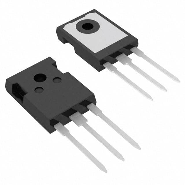
- Package: TO-247
- Essence: Power MOSFET for high power applications
- Packaging/Quantity: Available in reels of 1000 units
Specifications
- Voltage Rating: 1200V
- Current Rating: 24A
- On-Resistance: 0.19 Ohms
- Gate Charge: 80nC
- Operating Temperature: -55°C to 175°C
Detailed Pin Configuration
The IXTH2R4N120P follows the standard pin configuration for a TO-247 package: 1. Gate (G) 2. Drain (D) 3. Source (S)
Functional Features
- High voltage capability allows for use in high power applications
- Low on-resistance minimizes power loss and heat generation
- Fast switching speed for efficient operation
Advantages and Disadvantages
Advantages
- High voltage and current handling capability
- Low on-resistance for efficient power transfer
- Fast switching speed for improved performance
Disadvantages
- Higher cost compared to lower power MOSFETs
- Requires careful thermal management due to high power dissipation
Working Principles
The IXTH2R4N120P operates based on the principles of field-effect transistors, utilizing the control of electric fields to modulate the conductivity of the device. When a sufficient gate voltage is applied, the device switches on, allowing high power currents to flow through.
Detailed Application Field Plans
The IXTH2R4N120P is suitable for a wide range of high power applications including: - Switch-mode power supplies - Motor drives - Inverters - Welding equipment - Renewable energy systems
Detailed and Complete Alternative Models
- IXTH24N120P: Similar specifications with slightly higher current rating
- IXTH2R6N120P: Similar specifications with slightly lower on-resistance
This comprehensive entry provides an in-depth understanding of the IXTH2R4N120P, covering its basic information, specifications, pin configuration, functional features, advantages and disadvantages, working principles, application field plans, and alternative models.
Liste 10 perguntas e respostas comuns relacionadas à aplicação de IXTH2R4N120P em soluções técnicas
What is IXTH2R4N120P?
- IXTH2R4N120P is a high-power insulated-gate bipolar transistor (IGBT) designed for various technical solutions requiring efficient power control.
What are the key features of IXTH2R4N120P?
- The key features include a high current rating, low saturation voltage, fast switching speed, and high ruggedness.
What applications can IXTH2R4N120P be used in?
- IXTH2R4N120P is commonly used in motor drives, renewable energy systems, industrial automation, and power supplies.
What is the maximum voltage and current rating of IXTH2R4N120P?
- The maximum voltage rating is 1200V, and the maximum current rating is 40A.
How does IXTH2R4N120P compare to other IGBTs in its class?
- IXTH2R4N120P offers lower conduction and switching losses, making it suitable for high-efficiency applications.
What cooling methods are recommended for IXTH2R4N120P?
- Adequate heat sinking and forced air cooling are recommended to maintain optimal operating temperatures.
Can IXTH2R4N120P be used in parallel configurations?
- Yes, IXTH2R4N120P can be used in parallel to increase current-handling capability in high-power applications.
What protection features does IXTH2R4N120P offer?
- IXTH2R4N120P includes built-in diodes for freewheeling and overcurrent protection, enhancing system reliability.
Are there any application notes or reference designs available for IXTH2R4N120P?
- Yes, comprehensive application notes and reference designs are available to assist in implementing IXTH2R4N120P in various technical solutions.
Where can IXTH2R4N120P be sourced from?
- IXTH2R4N120P can be sourced from authorized distributors and manufacturers, ensuring genuine and reliable components for technical solutions.